

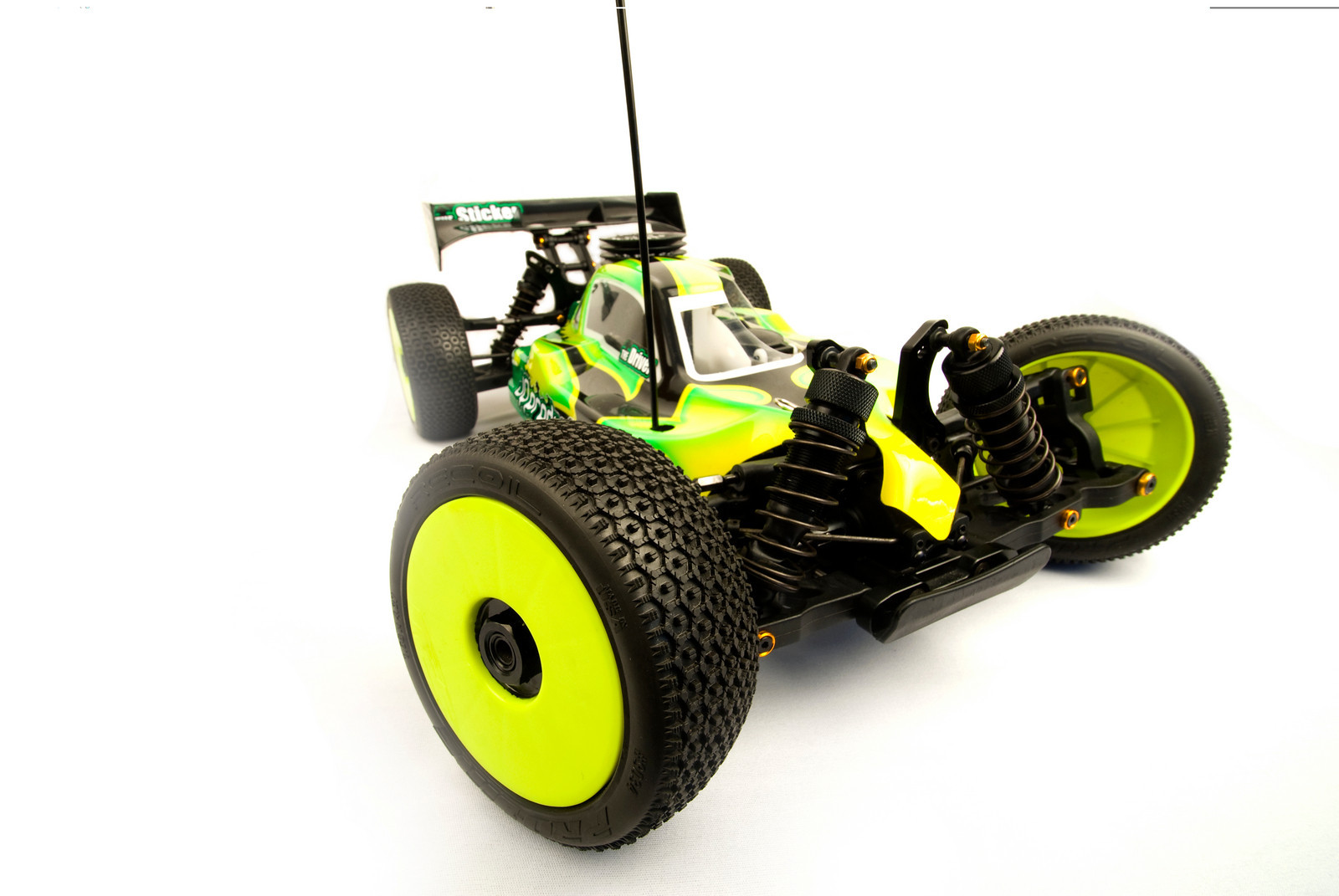
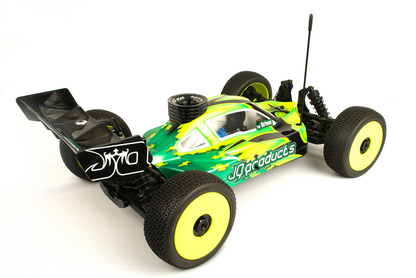
Part 1: First Photos and Specs
The original reason for designing THE Car was to make a car fast enough for me to win big races. For naturally talented racers the car itself isn’t such a big factor, but for racers like me, with low natural ability, the car has to be great, and suitable for my driving style, for me to win. Call me egoistic, but that’s why I started designing it. I thought that if I can make a car, prove to whoever I am racing for, that it’s better than what they have at that moment, maybe they would incorporate some of my ideas into their design, and I would become faster, and hopefully start winning bigger races.
Well, none of that worked out for various reasons, and I decided to start my own company and produce THE Car myself. I also realised that I needed to make sure that not only did this car need to be perfect for me, it also needed to suit all conditions, and all levels of drivers. It proved to be a lot harder to achieve than I thought. However, I believe I was able to create a car that everyone can be fast with, and which can be either super aggressive and fast, or very stable and easy to drive. Actually, it wasn’t just me, many of my friends, some top pros, some average racers, and some beginners, all helped to create THE Car. In the next 6 columns, I will explain how we did it:

Paint by Tanel Torger
THE Car Specifications:
Vehicle: 1:8 Nitro 4WD
Width: 307mm
Wheelbase: 324-328mm
Weight: 3240g*
Internal Gear Ratio: 3.90:1
*Weight measured with OS Speed, 2060 pipe, ProLine Rims, closed cell foam, Holeshot tyres, LRP 1600 LiFe Receiver Pack, Savöx Servos, Sanwa M11X Receiver
Part 2: THE Car Features Listed
– Narrow layout, along with one of the narrowest chassis ever seen on a 1:8 buggy. (108mm at widest point). A narrow car is more nimble and fast compared with a wider one.
– Central engine location. The key to building a narrow car.
– Revolutionary Adjustable Weight Distribution. Engine and Centre Diff move 8mm forwards-back.

– Laydown Brake System. In order to make the weight distribution change easily, and taking out the centre diff easily, laydown brakes was the way to go.
– Simplest throttle/brake linkage on the market. Because simple is always better.

– Balanced left to right. Because we turn both ways on our tracks.
– Out of the box, about 3240g. Because no matter what anyone says, a lighter car is faster, wears less, consumes less fuel, and less tyres, and it is the future of our hobby. If a heavy car is faster than a light one, the light one has the wrong setup or the wrong tyres!

– Failsafe servo saver for the threadlock challenged individuals out there. Impossible to work loose.
– The first un-complicated radiotray. Changing a servo in a hurry, with tray in the car is easy. Everything on the tray can be changed with the tray, and linkages intact.
– Distinctive rear end geometry for great on power traction, acceleration and cornerspeed.
– New style roll-centre adjustments on rear.

– Designed for European and American tracks and drivers. Possibility to set the car up for Euro style tracks and driving style, maximum cornerspeed, or US style jumps and bumps.
– Pre-assembled turnbuckles, because we all hate building them.
– 14.5mm threaded, hard-anodized shocks feature 3.5mm shafts. Because bigger isn’t better, better is better. We tested all sizes, and this is the best for THE Car.

·
– Hard Anodised CNC Aluminium Arm Holders with inserts for tuning toe-in, anti-squat and kick-up as standard. Since this is a Pro racing car, why should you have to immediately buy option parts?
– Optimized steering geometry for maximum, yet linear steering, and reduced bump-steer. Steering = Cornerspeed = Fast Laptimes = Wins. It’s all about steering.
– Moulded composite front and rear chassis braces. CNC may be option parts, because they aren’t needed, except for the people who like bling, “just because”.
– 3-shoe clutch, with aluminum clutch shoes.
– Lightened Aluminium 4mm hard-anodized chassis with ballast locations as standard. Because THE Car is underweight with lightweight options installed.
– CNC Aluminium Steering Knuckles as standard. Plastic ones are for RTR:s, even if they don’t break. We do have a certain bling requirement at JQ Products.
– Clunk style fueltank because we all crash, and it feeds fuel to the engine while upside down.
Part 3: My Goals, and Front-End Geometry
There is no point in making a car if it isn’t better than what’s already available. So what did I want to improve? I had three main performance-related goals for my car design, and every single decision I made regarding the design, I tried to think about how it affected these three points. Along the way I used websites to help with this process, one being similar to Low Offset that posts performance part reviews on REAL cars. But it was always great to read the articles and get insipirared for my little build!
1. Maximum steering in all situations. This was number one, because I felt that no car on the market had enough steering, steering always limited the maximum speed one could enter a corner, or drive through it. Only the old Crono had enough steering. So I knew if I made a car that has steering everywhere, I already had an edge on many of my competitors.

2. Corner Speed. Posting fast laptimes is all about cornerspeed. A ridiculous amount of steering isn’t enough, if the car lacks cornerspeed. It is hard to explain, but some cars turn into a corner, and then tend to want to stop, others just keep turning and going. This always perplexed me. I wanted to make sure THE Car maintained cornerspeed no matter who was driving.

3.Bump Handling. When the A-main comes around, and the track is bumpy, no driver can win with a bad handling car. This is a fact. Handling the bumps well had to be a priority for my design, and it proved to be the toughest challenge to conquer.

I had two main design related goal, and they were to:
·1.Keep It Simple!
I am not a fan of being innovative for the sake of innovation, or designing stuff which is more complicated than it needs to be, just in order to get a “wow” reaction when someone looks at it. Because that “wow” will fade when you are working on the car, fixing it between races, or when it falls apart in the main.
·2.Make it light!
All current cars are overweight. We have a minimum weight limit, so lets live by it! In some forms of racing, extra weight is added to the winner of the previous race, in order to slow him down in an attempt to make racing more exciting. Key words -> More weight = slower. Yes, also in RC, yes, also if you are a beginner, yes, also in clubraces. If a heavy car is easier to drive, faster, or better, it is because the light one has the wrong set up, or wrong tyres, not because more weight is better.
I also wanted to make it look good. But I would rather win with an ugly car, than be slow with the best looking car. And obviously I wanted to make it durable and strong, that goes without saying.
Suspension
Suspension geometry seems so simple, and most cars seem to be the same in this department, but there are differences. By suspension geometry I mean the length and position of the lower and upper arms, the shock positions, shock length, arm holder widths, and hub geometry. It is definitely not simple. THE Car is great but it’s not perfect. No car is. I can’t wait to start developing it further. For now the geometry is not completely off the charts, it shares a lot from current cars, but here I will highlight the main differences, and why I made it different.

 ·
·

Lower Arms
The lower arms are the shortest on the market. The reason for this is, that I always liked a short armed car more. Shorter arms make cars more responsive, but maintain stability when it comes to things other than driver input. For example, short arms make the car track straight in bumps, and make it less sensitive to changes, and surprising situations on the track. Also it helps a lot with steering, and jumping I think.

Long arms on a car gives it more traction, suspension movement, and a more slow reacting stable nature, but I believe to make a car get around a track as fast as the laws of physics allow, it needs short arms. The arms are also interchangeable left to right.
Arm Holders
Suspension Arm Holder width and arm lengths is something I played around with a lot. I tried many different combinations, and ended up with a set up, which is in fact the opposite to most other cars. THE Car has a wide front arm holder, and shorter arms than most cars. With this set-up I lost some steering, which you could say goes against one of my top 3 main goals for my car, but let me explain. Yes it reduced steering, but it enabled me to drive the car a lot more aggressively, and also set it up differently, to where it actually was faster. It jumped better, handled rough sections better, and was more stable and linear to drive. In sections with many jumps after each other, or woops, it would track more straight, and not go offline, if you messed up the first jump, it was easier to still make the second jump etc. So initially I lost steering, gained stability, but after more testing, I got the same steering as before, with more stability on rough tracks. It was a no brainer at that point.

C-Hubs
For the C-hubs in the front, I went with a similar design to the Losi XX-4 design, because it’s clever. I believe that was the first car with this front end geometry. Actually I also took a really close look at the old Crono cars, because they had the best steering of all cars. Bringing the point where the arm attaches to the hub, inwards (compared to the og. Kyosho style), and also vertically closer to the wheel centre, makes the car a lot more stable and less prone to flipping over. Also, it helps in the bumps and jumps, because as the suspension compresses, the wheels also move more inwards, and the suspension gets stiffer. You can feel this, as you press the front of the car down, it gets stiffer before the chassis hits the ground. I always liked that. And yes, the arms look just like the Losi’s, because another shape will not fit, it will rub somewhere, and there is no point in being different if it is worse.

Part 4: Rear End Geometry

Rear Arms
The Rear Arms are super short compared to all other cars. That’s simply because they are the same length as the front arms, which because of the front end geometry I ended up with, are also really short. The arm holders on the rear are not as wide as the front. They are old school, medium width. Nothing special there, except, if you draw a line viewing from the bottom, co-linear with the front hingepins, it intersects the rear hingepins halfway between the rear arm holders. Also the outer arm-to-hub attachement line intersects, and the upper link locations also. Something maybe only in my head, or then something that really makes the car work more as one. But in any case, in testing, the best set-ups have tended to be where the front and rear links are also equal. THE Car feels balanced and predictable with linear steering. By linear steering I mean, the same throughout the corner, and smooth even as speed increases or decreases, so no sudden changes in the amount the car turns. I think this is due to the fact that the front and rear ends are in-sync. They are afterall bolted to the same chassis, so they shouldn’t be too different, or else they will end up working differently from each other. This is my opinion. My goal was to try and make the front and rear roll the same in corners, have similar traction, and act the same in all conditions and speeds. All in all, I found that these short arms gave THE Car a lot more steering and just made it plain FAST!


Rear Hubs
The hubs are quite different to anything else on the market. I wanted to have the same offset on the rear as on the front. By offset I mean the distance between the arm to hub attachement and the centre of the wheel. In order to get the same offset, the hubs now clearly have a lot more offset than all other cars (actually opposite to many, meaning the attachment is on the inside of the wheel centre, not outside). This increased rear traction a ridiculous amount. First I had too much, the thing wouldn’t turn anymore. But what I ended up with was, the car could be set up with more aggressive steering, yet when exiting a corner, and getting on the gas, the rear end would just square up (straighten out) quickly, and have crazy forward bite. The rear hubs is the one thing that made me most excited when testing, because when I tried them back to back with standard hubs and arms early on, they felt like crap, but the stopwatch thought otherwise! The problem with them was, that the car could do unexpected things when it got out of shape, and it was not good in bumps. This was because it required a very different set up compared to conventional cars, and different shock positions. I managed to solve these issues, and ended up with a car that has superior corner speed, forward bite, and acceleration out of corners. I bet there will be other cars with more offset on the rear hubs and short arms in the future.


Rear Roll Centre Adjustment
Another unique thing about the rear end geometry is how there are vertical holes on the rear arms, as well as on the hubs. There are actually 3 holes in the arms, but that is just so that the arms work on both sides of the car, so only 2 holes are used, middle and top. The reason for this is so that the suspension, up and down travel and ride height, will be unchanged, regardless of which hole is used. On other cars it’s always a problem with one of the set ups, either there is not enough up travel, or down travel, or the shock end needs to be changed etc. That’s all it is, easier to make the adjustment, the result is the same as on other cars. Or so I thought! Actually it is similar, but not quite the same. But in any case, the top hole gives the car more traction and makes the suspension stiffen up more when compressed, the lower hole reduces traction, and the rear end will slide more. As for bumps, that comes down to preference, some prefer the upper hole, some the lower.

Just in order to make it confusing though, in testing I found, that most of the time, I got even more traction when I used the top hole in the hub, and the middle hole in the arm. This set up made the rear end of THE Car seem like it was sucked down on the ground, not only when cornering or accelerating, but quite surprisingly, also in bumps and jumps, it stayed flatter, and didn’t hop around as much. The only logical explanations for this increase in traction, that I could think of, is that the upper link is lower compared to the inner arm attachment, and the piston position and movement is slightly different. In any case, the rear end is adjustable enough that anyone can find their preferred set up, no matter what their driving style is. I will create an extensive set-up guide for this, and all other features on THE Car.
·
On THE Car you can set the rideheight with clips, or threaded collars, to each his own…

Part 5 Steering, Shocks and Radiotray Simplicity
Steering


Shocks
“Bigger isn’t better, better is better.” That’s a quote I saw somewhere, and I just think it suits this topic well. Fioroni and HongNor made shocks which were slightly bigger than others, and they worked better. Then Losi made shocks a lot bigger than the others, with 15mm pistons, and they were even better. Suddenly everyone started making bigger and bigger shocks and at some point stopped thinking about how they work. In the past, cars were heavier, wider, and had small shocks, now they are lighter and more narrow, and have big shocks, sounds backwards to me, and I think it is. I found what I believe to be the best size for a shock, on a light narrow, nimble car, 14.5mm piston diameter. I don’t believe in carrying any unnecessary weight around, and I want my suspension to respond to small bumps, as well as the big ones.


Radiotray
I have always been of the opinion that it doesn’t matter how easy it is to remove the radiotray from the car, if you need an engineering degree and tweezers to change a servo once the tray is out. If I am at the track, and I want to change a receiver, transponder, servo, whatever, I do not want to have to remove the radiotray from the car in the first place. I want to just remove the component I want to change.

On the other hand, if I am cleaning the car, and I have to unscrew 7 screws instead of 4, to get the radiotray out, it will not make me mad. This is why I designed the radiotray in a way that it is easy to remove either servo, transponder, or battery, simply, without removing anything other than the part you want to change, and the receiver or batterybox lids. There are no small parts or nuts to fiddle about with, no small openings for wires to go through, just a really simple layout.


Part 6: Weight Distribution Funkyness
Weight Distribution (Engine Mounts)
Weight distribution is a key feature when thinking about a cars performance. Since we aren’t racing in a circle, and actually turn in both directions, left to right weight balance is as close to equal as possible. However, front to back weight balance can be altered. Basically, a car with weight far forward, will jump really well, (throw a hammer head first), it will push on power and at speed (slide a hammer fast in a circle head first, front will push out), but will turn well at low speed (weight = traction, not enough speed to push front end out). A car with weight far back will not jump as well (throw hammer with handle first), it will have more steering on power and at speed (slide hammer fast in a circle with handle first, rear will slide out), but it will turn less at low speed (weight = traction, not enough speed to push rear end out). As for bump handling, I believe both can be really good, weight forward, or weight back, that depends on the set up. However, it is more common, that cars with the weight further back feel more stable and better on really challenging tracks. This is specially true for beginners or hobby level drivers. A car with the weight further back will be easier to control as it has more rear traction.

So where to put the weight? I believe that depends on your driving style. Solution? Adjustable Weight Distribution. THE Car is designed so it is possible to move the centre diff-mount, and engine 8mm forwards and backwards. This makes a huge difference in the handling of THE Car. The advantage of having this unique adjustment available, is that now it is possible to set up the car to perfectly suit each track. At major events changing a chassis to a different design, is not allowed, and if it is allowed, it’s a lot of work. On THE Car it can be done on the same chassis, in a few minutes. This has proved to make up to 0.5s changes in average laptimes which I am sure you will agree is A LOT! Basically, jumps, hairpins, technical, = weight forward, fast, speeping corners, bumpy, weight back. But to each his own, be brave, try it out for yourselves!
Additionally, the chassis has locations for weights, which can be secured with a sinlge M3 countersunk screw. These weights will be available at a later stage as option parts. When building the car with optional lightweight items, which will also be available later on, THE Car will be under the weight limit. Then each driver can choose where to place the additional ballast, in order to bring THE Car back up over the weight limit. There are locations at the front and the back of the chassis. This way the centre of gravity of THE Car is as low as possible, and the longitudinal balance can be adjusted by the driver.
Centre Diff Mount
This is my proudest creation along with the Adjustable Weight Distribution. But unfortunately one that is now not anymore completely unique. The centre diff mount was the second part assembly I designed for THE Car back in 2006, right after the radiotray. Back then I hadn’t seen a laydown system before. And this is what I came up with.

Again, I wanted to keep it simple. I use only one link for the brakes, which makes it really easy to move the diffmount forwards and backwards. Also, the centre diff can be taken out without messing about with the brake system. I chose to make the mount aluminium for 3 reasons:
1. It saves space
2. It is strong, stiff, and consistent in hot weather, heat from the engine, and friction from
brakes.
3. It looks cool
![]()
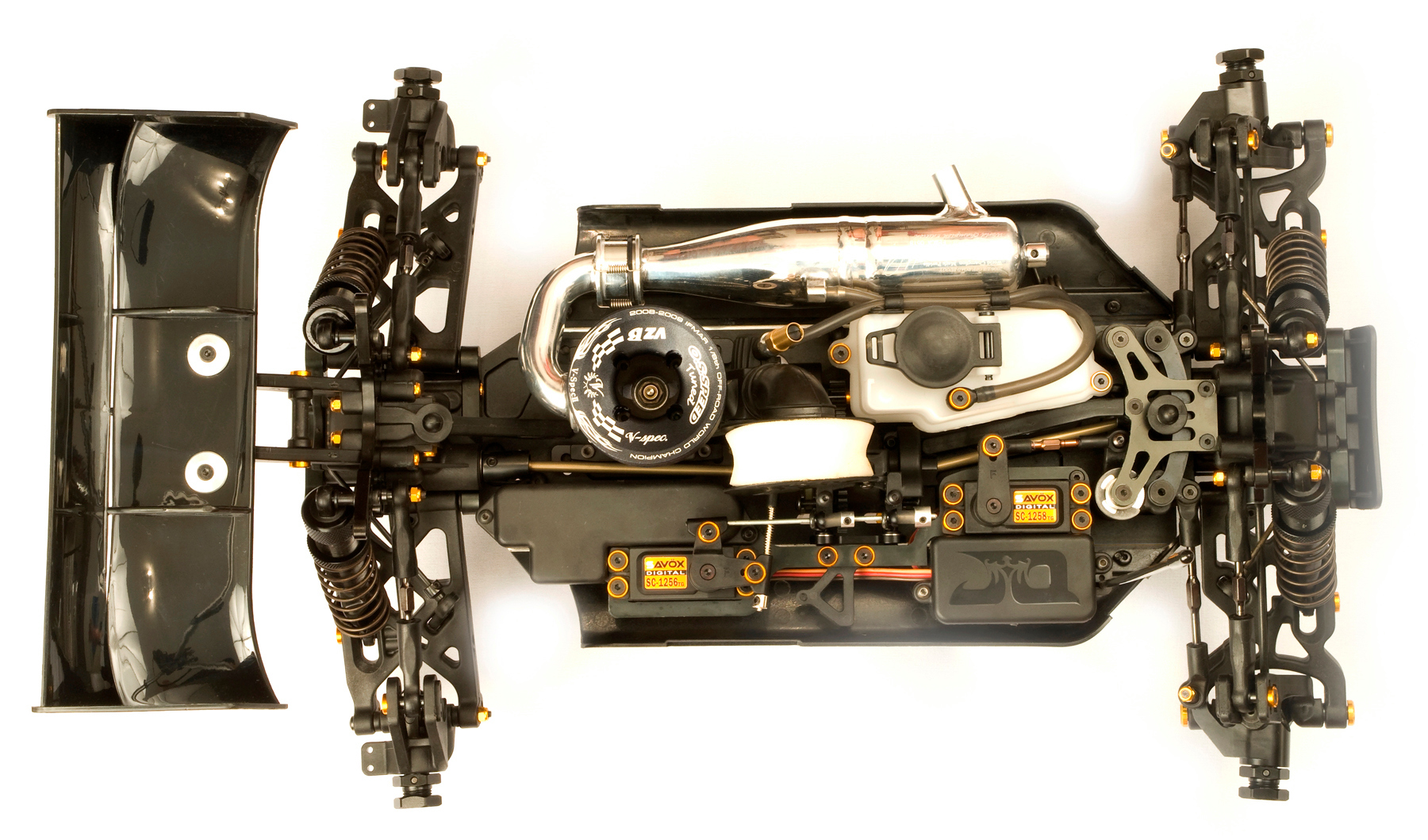
THE Release Part 7: Drivetrain, Fueltank and Aerodynamical Beauty
Drivetrain
The Drivetrain is a key feature in any racing car. On THE Car I focused on two main points, making it light, and making it durable. I want to have a free spinning, maintenance free drivetrain, and I want it to be light.The drivetrain may seem insignificant at first, but it’s not, it directly affects the cars acceleration and responsiveness, and also as I have found in testing, runtime.
Driveshafts
I have never liked the so-called CVD:s. Personally I believe they are used mostly because they are cheaper to manufacture, and because they are trendy now. In my opinion the cons clearly outweigh the pros. They wear out faster, they work differently when worn out and when new (inconsistent), they require more maintenance, they require larger bearings and bulkier hubs, unless you want to loose pins. So I went with the bulletproof universal joint. For me it was a simple choice.

Diffs
As far as the diffs are concerned, I wanted to make strong, good, basic diffs to start out. Later on we can start playing about with other versions. So how make them better? I made them as light as possible, and I challenge you to find a car with lighter diffs than what you can find in THE Car. You won’t! At least not during 2010, I can assure you. Lighter diffs = less rotating mass, = faster acceleration and throttle response, and more fuel mileage. I also made sure to have enough oil in the diffs, we don’t want to cook them, so they have the same amount of oil as the other top brands.

Fuel tank
The fuel tank is a fairly standard new generation tank, with an airplane style clunk pick up system, so the engine gets fuel also while the car is upside down. It also has fuel line clips attached to the side, 1cc and 2cc inserts for adjusting the volume, and a built in splash guard to stop fuel getting on the brakes.

The only real innovation is how the pressure line doesn’t have its nipple on the cap, but instead has its attachment next to the cap. This was done in order to protect the pressure line from damage, making it possible to cut a smaller hole in the body, and just because the cap looks much cooler without it.

· The cap and spring weren’t finished for these pics, but you get the idea.
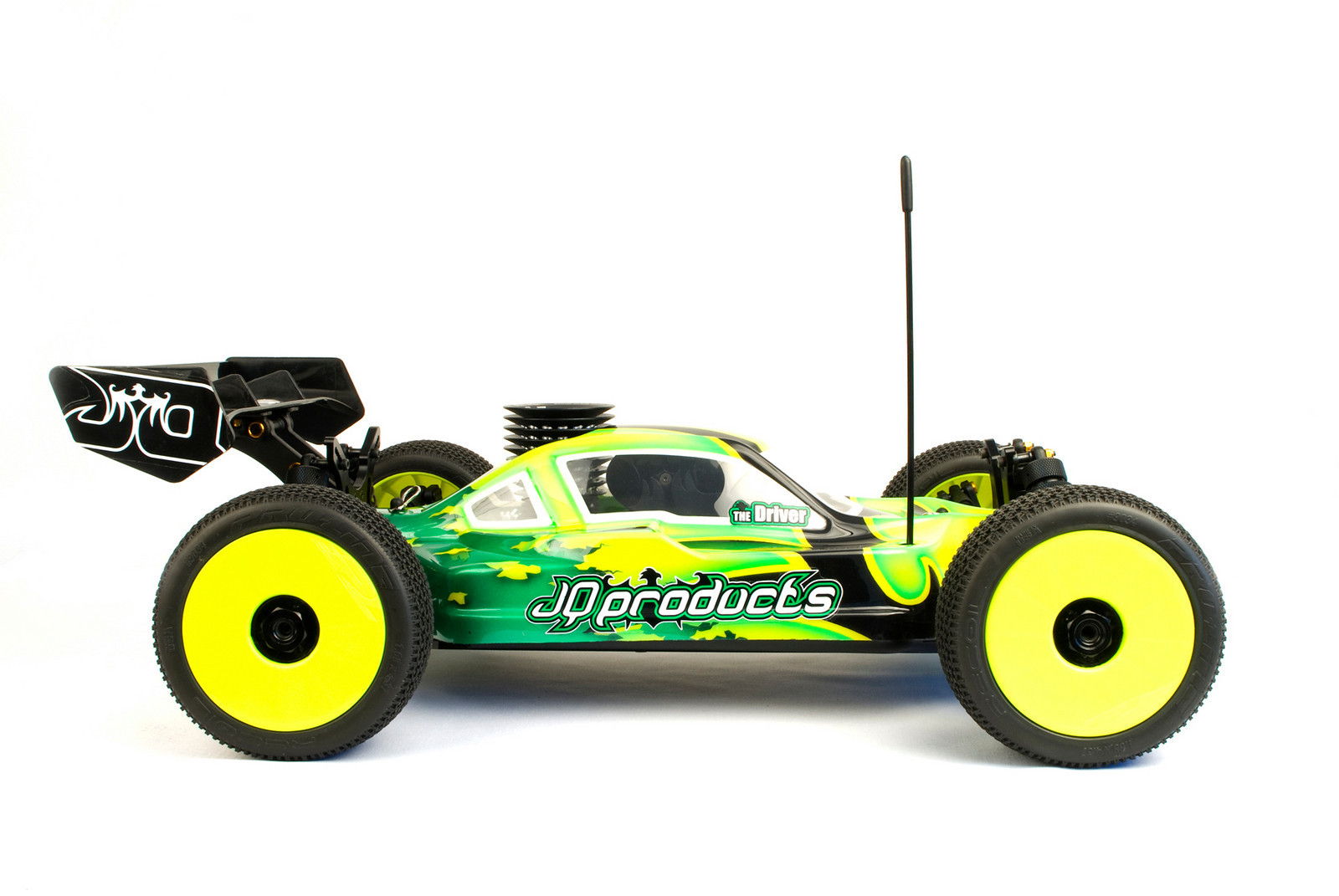
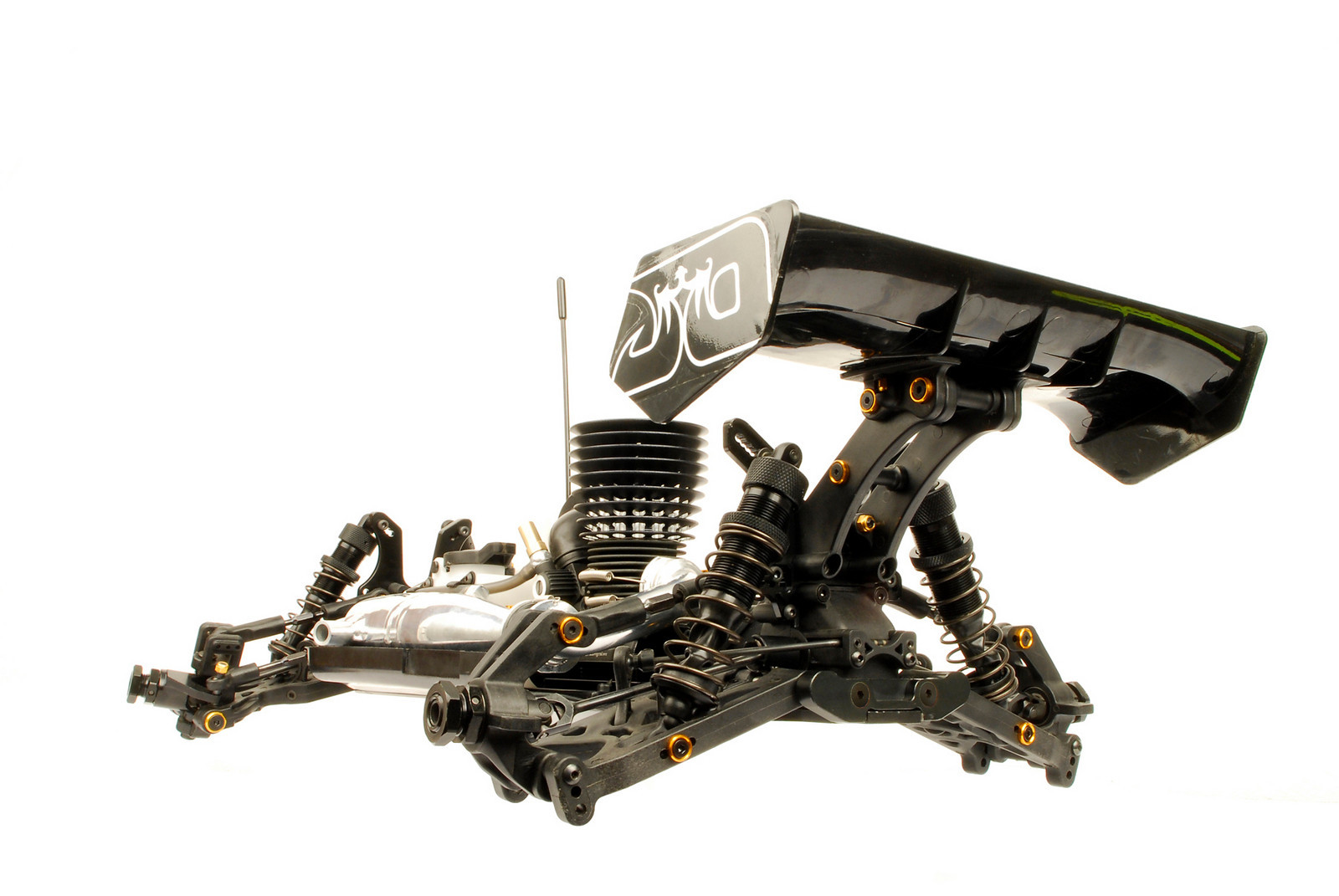
Body and Wing

THE Wing was not wind tunnel tested, because I am not an aeronautical engineer, and because THE Car in front of the wing makes everything rather complicated. Instead it was designed to look really cool and fast, be light, and at least in theory create downforce, instead of acting as a weight, and airbrake. It is pretty much an airplane wing upside down with a few tweaks. Does it look cool? So far I have only heard positive comments, and I am rather stoked about that.


THE Body was designed purely based on looks, and I wanted to make it look like a car. I think it does. I cannot notice any performance difference with buggy bodies, other than the visually induced performance issues. (A good looking car is faster)


No slop wheel attachment
The wheels on a 1:8th scale buggy tend to wobble a lot. I decided to address this problem. What is the point of setting camber and toe in, if the wheel moves about so much that it changes the angles +/- 3 degrees? The solution proved to be really simple. By making the hole in the driveshaft elongated towards the inside, the hex pin can now move inwards. This means, that when the grubscrew in the axle is tightened, it forces the pin, and the hex along with it inwards, towards the wheel bearing. In order for the bearings not to be crushed together, I then added a spacer between them. Simple and effective. No more extra slop in the wheel attachment. Because we aren’t rocket scientists at JQ Products, and because this area involves a lot of variables to get the tolerances right, we had to include 0.1mm shims, that need to be used in the case that after tightening the grubscrew, the bearings tighten up. Pay attention to this when building THE Car.
What else?
We hope you like THE Car. If you don’t, why did you read this far? HAHA. If you have any questions or concerns, the absolute best way to get any sensible responses is to contact us directly!